

Driver-information diagnosis in Dubai
Range Rover Instrument Cluster Repair in Dubai
A blank display, flickering panel, incorrect gauge or warning message can come from the instrument cluster, but it can also begin at the battery, a sensor, another control module, the vehicle network or a damaged connector. We compare the real vehicle condition with the data reaching the panel before repair, coding or replacement is approved.
The display is the final step in a larger information path
An incorrect gauge does not automatically mean the panel is faulty
The instrument cluster presents information that is created elsewhere in the vehicle. Speed, fuel level, coolant temperature and many warning requests usually begin at sensors and other modules. The network carries that information to the cluster, which processes it and turns it into gauges, graphics, lamps, messages and sounds.
If one gauge is wrong while the rest of the panel works, the source data must be compared with the displayed result. If the entire cluster is blank, power, ground and network wake-up come first. If the display flickers after a battery event or after the cabin becomes hot, supply history and internal cluster condition become more important.
This page covers broad Range Rover and Land Rover cluster, display, gauge, coding and replacement intent. The Range Rover Sport cluster page should remain model-specific and should not duplicate this broad service page.
Start with what the driver can see
Six cluster symptoms and the first question each one raises
The entire cluster is blank
The first question is whether the panel has stable power, ground, ignition wake-up and network communication. A dark display does not prove internal failure until those conditions are checked.
The panel flickers or restarts
The first question is whether voltage changes, connector movement, cabin heat or an internal fault occurs at the moment of the reset. A video of the complete panel can preserve the pattern.
One gauge reads incorrectly
The first question is whether the source sensor and related module report the correct value. The cluster may be displaying incorrect information that it received faithfully.
Warning lamps remain on
The first question is which module requested the warning and why. The cluster may be presenting a valid request from another system rather than creating the fault itself.
Pixels, graphics or backlight fail
The first question is whether the hidden information remains available through scan data or other display functions. Local screen or illumination failure becomes more likely when the data path remains intact.
A replacement panel does not work correctly
The first question is whether the hardware matches the VIN, model year and fitted equipment. A similar-looking cluster may still be incompatible or incorrectly configured.
Trace the information from vehicle to driver
Six layers can affect one instrument-cluster symptom
The cluster is the final presentation layer. The source of a wrong display can be several stages earlier. The three rows below follow the information path and state what must be proven at each point.
Power, ground and wake-up
Stable battery voltage, intact fuses, dependable grounds and the correct ignition state allow the cluster to wake and remain active.
Required proof: supply and ground remain stable while the blank, flicker or reset complaint is present.
Sensor and source-module information
Speed, fuel, temperature and warning information usually begins at sensors or control modules outside the instrument panel.
Required proof: the source data agrees with the real vehicle condition before the display is judged.
Vehicle-network delivery
The information must travel through the vehicle network without missing, delayed or corrupted messages. One communication problem can affect several displayed functions.
Required proof: the cluster and related modules remain online during the failed condition.
Cluster processing and logic
The cluster interprets the received data, applies the vehicle configuration and decides how each gauge, warning and message should appear.
Required proof: correct data reaches the cluster but the panel interprets or presents it incorrectly.
Display, illumination and gauge output
Pixels, graphics, backlighting, warning lamps, sounds and gauge movement must present the processed information clearly and consistently.
Required proof: the underlying information is present but the physical display or gauge output is defective.
Vehicle identity and configuration
A repaired or replacement cluster must match the exact vehicle, fitted equipment and communication relationship.
Required proof: part identity, menus, warnings and displayed functions match the VIN and fitted specification.
Compare the information path at one moment
What the diagnostic bench must compare
The panel should not be judged from appearance alone. The useful question is where a value first becomes wrong, disappears or stops updating as it travels from the vehicle to the driver.
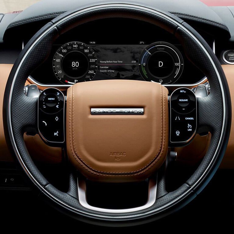
Trace the value until the evidence changes
A gauge or warning can be incorrect even when the screen is working normally. The workshop compares the real condition, the source-module value, the message delivered to the cluster and the final display. The first disagreement identifies the layer that needs repair.
Real vehicle condition
Confirm what is physically happening outside the display, such as actual fuel level, temperature condition, vehicle movement or ignition state.
Mismatch means: the investigation begins before the cluster and must not rely only on the displayed value.
Source-module data
Read the value produced by the relevant sensor or control module and compare it with the real condition.
Mismatch means: the sender, source circuit or related module may be creating the incorrect information.
Network delivery
Confirm that the required message reaches the cluster consistently while the fault is present.
Mismatch means: communication, connector or network wiring must be resolved before the panel is blamed.
Panel output
Compare valid incoming information with the gauge, warning, graphic, illumination or sound presented to the driver.
Mismatch means: cluster processing or physical output becomes the supported repair area.
The decision must follow the first failed comparison
Repair the source when the value begins wrong, repair the communication path when the message is lost, and consider cluster work only when valid information reaches the panel but is processed or displayed incorrectly.
Five controlled passes from complaint to proof
How the workshop diagnoses an instrument-cluster fault
Each pass has one job. The workshop should not move to cluster repair, coding or replacement until the result of the current pass is clear.
Preserve the complete failed state
Capture the exact display condition before battery disconnection, code clearing or repeated restarts change the evidence.
Record affected gauges, warnings, menus, pixels, illumination and sounds. Note ignition state, cabin heat, driving condition and recent battery, windscreen or dashboard work.
The complaint is classified as one failed output, a total shutdown, an intermittent reset or a warning requested by another module.
Prove power, ground and wake-up
A blank or restarting panel cannot be judged until its electrical supply remains dependable during the fault.
Assess battery and charging condition, relevant fuses, grounds, ignition wake-up and cluster feeds while the failed condition is present.
Low voltage, voltage drop or interrupted supply is either identified as the cause or excluded with measured evidence.
Follow the value from source to screen
The real condition, source data, network message and displayed result are checked in the same diagnostic path.
Compare speed, fuel, temperature and warning information from the relevant module with the real vehicle condition and the value shown to the driver.
The first point where the information becomes wrong identifies the source, communication or cluster layer that needs repair.
Capture intermittent communication or internal failure
Heat, connector movement and vibration must be linked to the event rather than inferred from an old stored code.
Review related-module communication, connector condition and moisture evidence, then recreate the relevant heat, ignition or movement condition where safe.
The dropout, connector fault or internal panel failure is observed while it happens and can be repeated or supported by consistent evidence.
Repair the failed layer and retest the complete panel
The final test must prove more than a screen that turns on. Every affected driver-information function is checked.
Complete the approved source, wiring or cluster repair. Apply only the configuration required by the verified hardware and vehicle, then retest gauges, warnings, menus, illumination, sounds and communication.
The original complaint no longer returns under the same condition and the panel again provides dependable driver information.
Replacement approval rule
Do not approve a replacement cluster until stable supply, valid source information and dependable network delivery have been proven. The report should state which internal display, processing or output function failed.
The failed layer determines the repair
Choose the instrument-cluster route supported by the evidence
The three routes below solve different problems. The correct route is the one that matches the first proven failure in the information path.
Repair the source or wiring
Choose this route when the panel is presenting incorrect or missing information that began at a sensor, source module, power feed, ground, connector or network circuit.
Repair the original cluster
Choose this route when valid information reaches the panel but a confirmed display, illumination, gauge, connector, memory or circuit-board function fails inside the original unit.
Replace and configure the cluster
Choose this route when the original panel is not dependable or repairable and a compatible replacement has been identified for the exact vehicle and fitted equipment.
Do not move directly from symptom to replacement
A blank screen, warning lamp or incorrect gauge is not enough by itself. Replacement becomes the supported route only after the source, supply and network paths are proven and the original cluster is confirmed unsuitable for dependable repair.
Coding should match verified hardware to the vehicle
What cluster coding and configuration should address
Identify and match
The original and replacement cluster should be identified from the VIN, part information, model year and fitted equipment. Similar appearance is not proof of compatibility.
- Vehicle identity
- Hardware and part relationship
- Analogue, mixed or digital display type
- Fitted menus and driver-information features
Configure and communicate
The verified cluster should present the correct functions and exchange information with the modules that provide speed, fuel, temperature, warnings and other driver data.
- Menus and displayed features
- Warning requests and network relationship
- Gauge and message behaviour
- Controlled data handling within the legitimate repair scope
Verify the complete panel
After coding or configuration, the workshop should test the complete driver-information system rather than checking only that the display turns on.
- Gauges, graphics and illumination
- Warning lamps, messages and sounds
- Communication with related modules
- The original intermittent or incorrect-display complaint
Coding cannot repair a physical fault
Configuration does not correct weak battery voltage, poor grounds, damaged wiring, failed sensors, missing network messages, dead pixels, backlight failure or internal gauge hardware. Those faults require diagnosis and repair at the layer where the information path actually fails.
Common shortcuts create repeat faults
Instrument-cluster problems commonly misdiagnosed
Low voltage treated as panel failure
A weak battery or unstable charging system can cause flicker, resets and several warnings. Supply stability should be established first.
Incorrect fuel gauge treated as display failure
Fuel-level sensing, wiring or source-module data may be wrong while the cluster presents the received value correctly.
Warning lamp treated as a cluster fault
The panel may be responding to a valid request from another control module. The system that requested the warning must be diagnosed.
Blank cluster treated as proof of internal damage
Missing power, ground or network wake-up can leave a healthy panel dark. Connector and supply checks come first.
Used cluster fitted without compatibility planning
A similar-looking unit may not match the vehicle identity, hardware, network or displayed features.
Intermittent evidence lost before inspection
Flicker and reset faults can disappear in the workshop. A clear video showing the complete panel and ignition state can preserve the pattern.
Cluster design changes across generations
Range Rover instrument panels vary by model and fitted display system
Range Rover, Range Rover Sport, Evoque, Velar and Land Rover models use different analogue, digital and mixed instrument panels, network architectures, warning strategies and driver-information features. A cluster should be identified from the VIN, model year, part data and fitted equipment rather than from appearance alone.
Previous battery failure, water exposure, dashboard removal, windscreen work, collision repair and accessory wiring can influence the fault. A model-specific Range Rover Sport instrument-cluster page should support that vehicle without repeating this page’s broader diagnosis and coding intent.
Analogue and mixed displays
Gauge motors, illumination, warning lamps and central displays can fail independently and need separate evidence.
Digital instrument panels
Graphics, processing, network data and software relationship become central to blank, distorted or restarting displays.
Previous dashboard or windscreen work
Connector movement, moisture or accessory wiring can create faults that appear after an unrelated repair.
The failed layer determines the quotation
What affects Range Rover instrument-cluster repair cost
The scope depends on the vehicle, cluster type, affected display function, power and network findings, internal damage, water or heat exposure, original data condition, repairability and configuration requirements. A backlight repair, source-circuit repair and complete digital-cluster replacement are different jobs.
A useful quotation should state whether the source data is valid, what proves the cluster itself, whether the original unit communicates, what internal function is being repaired and how configuration and final verification are included. Fixed prices and completion times should not be copied from another cluster before inspection.
- VIN, model year and exact cluster identification
- Battery, charging and power-supply findings
- Source-data and network comparison
- Display, gauge, illumination or processor fault
- Repairability or replacement evidence
- Configuration and vehicle-data requirements
- Final gauge, warning and display verification
Dubai conditions can expose intermittent display faults
Heat, voltage stress, moisture and previous dashboard work change the pattern
High cabin temperature can expose a marginal display, connector or internal circuit. A weak battery or unstable alternator can trigger resets and several warnings. Moisture after windscreen or dashboard work can affect connectors, while accessory wiring can disturb supplies or communication.
Tell the workshop whether the fault appears after parking in heat, after a flat battery, during starting, following windscreen work or only while driving. Record a video that includes the full panel, ignition state and warning message. Do not clear fault records repeatedly before diagnosis.
Instrument-cluster questions
Frequently asked questions
Does an incorrect gauge always mean the instrument cluster is faulty?
No. The source sensor, related control module, network message or wiring may be wrong while the cluster displays the received value correctly.
Can a weak battery cause cluster flicker or resets?
Yes. Low or unstable voltage can affect cluster wake-up, communication and internal processing. Battery and charging condition should be checked first.
Can a Range Rover instrument cluster be repaired?
Some confirmed display, illumination, connector, memory or circuit-board faults may be repairable. Suitability depends on the unit, damage and the ability to verify it afterward.
Does a replacement instrument cluster need coding?
It may require vehicle identification, configuration and network relationship work according to the exact vehicle and cluster. Installing the hardware alone may be incomplete.
Can I drive with a blank or faulty cluster?
A failed cluster can prevent you from confirming speed, fuel, temperature and critical warnings. Arrange inspection and do not rely on unavailable information.
Why do warning lights stay on when the vehicle seems normal?
The cluster may be displaying a valid request from another module or a communication fault. The source system and stored faults should be diagnosed.
What should I send before booking?
Send the VIN, model year, photos or video of the full cluster, exact warning, affected gauges, battery history and details of recent dashboard or windscreen work.
Book instrument-cluster diagnosis in Dubai
Compare the real vehicle condition with the displayed information before replacing the panel
Send the VIN, full-panel video, exact warning and battery history. The workshop can then advise what must be tested before cluster repair, coding or replacement is approved.