The short answer
A Range Rover fault code is a record of what a control module detected, not a verdict on which part failed. Read the complete code, its suffix, the module that stored it, its status and the conditions recorded at the time. Then test the circuit, signal or mechanical system named by the code.
A five-character DTC such as P0299 or U0121 narrows the search. A JLR-aware scan may add a two-character suffix such as -64 or -87. That extra detail can separate a plausibility fault from low voltage, an open circuit or a missing message. Searching only the first five characters can remove the most useful part of the result.
The dashboard warning and the stored code are related, but they answer different questions. If you need to decide whether a red or amber message is safe to drive with, use the Range Rover warning lights guide. This page owns the fault-code lookup and interpretation task.
What this index covers
Every main DTC family, the code structure, scan status, module context and a broad quick-reference list of commonly searched generic and Range Rover-relevant codes. Each row also gives a sensible first testing direction.
Why no static page can list every JLR code
There are thousands of generic and manufacturer-defined codes across model years, engines, transmissions, body systems and software levels. Some descriptions change with the recording module or suffix. An honest lookup must use the exact vehicle and full scan report.
Code families
What P B C and U identify
The first letter identifies the broad diagnostic family. It does not tell you which control module recorded the fault or whether the fault is active now.
PPowertrain
Engine, transmission, emissions and hybrid powertrain monitoring. Generic OBD readers concentrate heavily on this family.
BBody
Restraints, access, seats, climate, lighting and other cabin or body functions. Manufacturer data and the module name matter.
CChassis
Brakes, stability control, steering, suspension and wheel-speed information. Keep any suffix shown by the scan tool.
UNetwork
Lost communication, invalid data and control-module results. The module reporting the U code is often the receiver, not the cause.
Read the complete result
How to decode a Range Rover fault code
The SAE J2012 framework defines standard DTC formats and descriptions. Modern manufacturer diagnostics extend that framework. Ownership cannot be decoded reliably from one digit in every case because allocations have evolved, so confirm the description against the exact vehicle application.
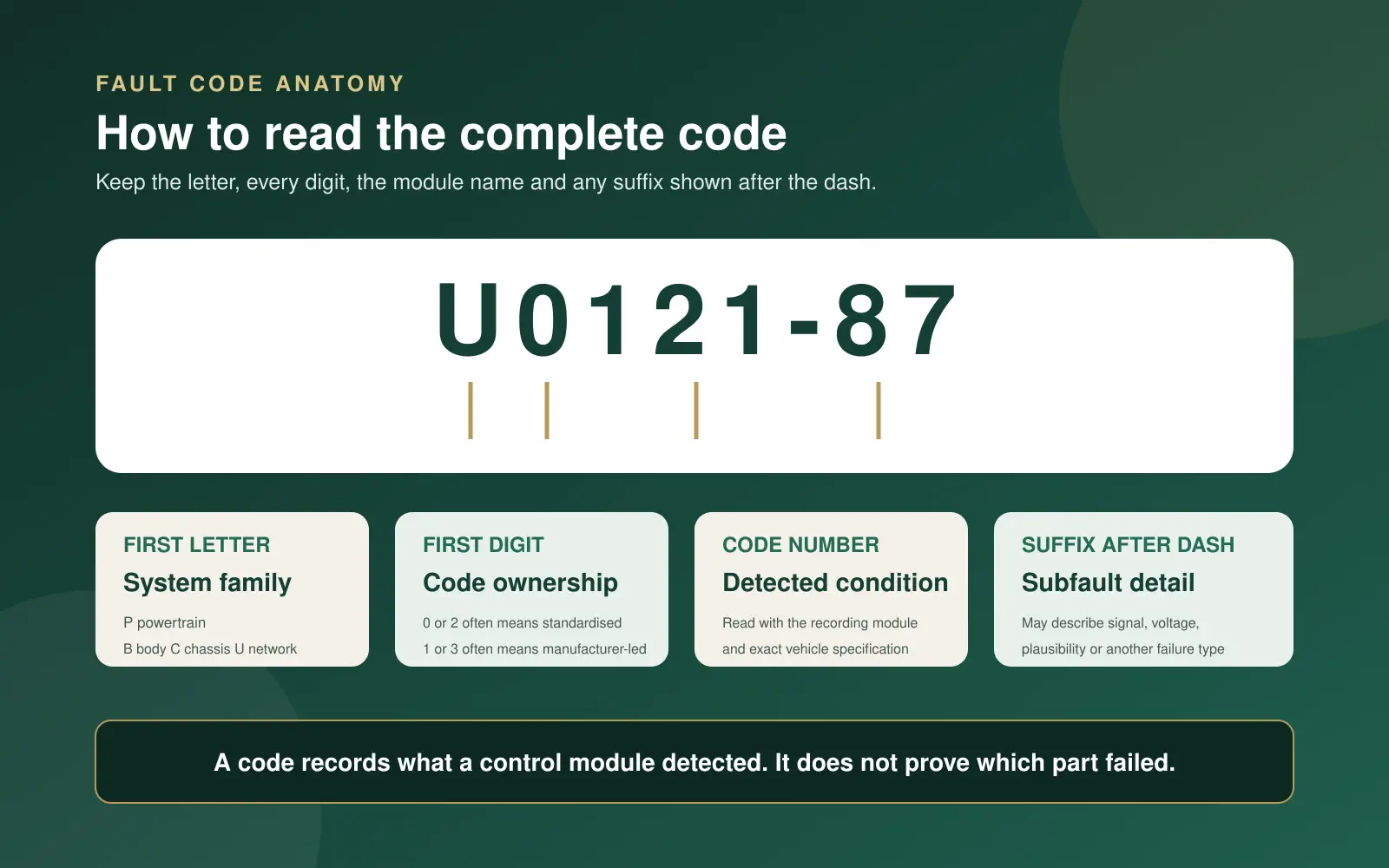
The first letter
Identifies the broad P, B, C or U family.
The next four characters
Identify the assigned condition. Some are standardised and others depend on the manufacturer.
The suffix
Where supplied, it refines the failure type. Keep it exactly as shown, including the dash.
The recording module
Tells you which control unit made the decision. The same code reported by another module can change the test path.
Useful powertrain code ranges
Searchable reference
Range Rover fault code index
Search by code, system, description or testing direction. This practical index is not a substitute for the exact JLR diagnostic database for the vehicle.
| Code | Usual module | What it identifies | First testing direction |
|---|---|---|---|
Bxxxx | Body, restraint, climate or access module | A body-system condition whose wording is often manufacturer and module specific | Use the complete code, suffix and module. Do not use a generic B-code list to approve airbag or restraint work. |
P0001 | Engine control | Fuel volume regulator control circuit open | Check the regulator circuit, connector, power supply and command before condemning the pump. |
P0002 | Engine control | Fuel volume regulator control range or performance | Compare commanded and actual rail pressure, then test supply, return and regulator response. |
P0003 | Engine control | Fuel volume regulator control circuit low | Test circuit voltage, resistance to ground and the regulator current draw. |
P0004 | Engine control | Fuel volume regulator control circuit high | Inspect for an open circuit, poor terminal contact or an incorrect high signal. |
P0010 | Engine control | A camshaft position actuator circuit on bank 1 | Check oil condition, actuator supply, wiring and commanded cam timing. |
P0011 | Engine control | A camshaft timing over-advanced or system performance on bank 1 | Compare desired and actual timing, then check oil pressure, VVT control and mechanical timing. |
P0012 | Engine control | A camshaft timing over-retarded on bank 1 | Check oil level and quality, VVT operation, sensor data and timing alignment. |
P0013 | Engine control | B camshaft position actuator circuit on bank 1 | Test the actuator circuit and verify that exhaust cam timing follows the command. |
P0014 | Engine control | B camshaft timing over-advanced or system performance on bank 1 | Check oil control, VVT response and mechanical timing evidence. |
P0016 | Engine control | Crankshaft and camshaft correlation on bank 1 sensor A | Preserve startup data, verify oil pressure and sensor signals, then check timing correlation. |
P0017 | Engine control | Crankshaft and camshaft correlation on bank 1 sensor B | Compare crank and exhaust cam signals before considering a sensor or timing repair. |
P0018 | Engine control | Crankshaft and camshaft correlation on bank 2 sensor A | Check bank 2 cam response, sensor circuits, oil control and mechanical timing. |
P0019 | Engine control | Crankshaft and camshaft correlation on bank 2 sensor B | Use scope or scan correlation data to separate signal, VVT and mechanical causes. |
P0087 | Engine control | Fuel rail or system pressure too low | Compare low-side supply and rail pressure under load, then check restriction, leakage and control. |
P0088 | Engine control | Fuel rail or system pressure too high | Check the pressure sensor, regulator command, return path and actual pressure with approved equipment. |
P0089 | Engine control | Fuel pressure regulator performance | Graph requested and measured fuel pressure through the condition that sets the code. |
P0100 | Engine control | Mass or volume air flow circuit | Inspect the intake path and circuit, then compare airflow with engine speed and load. |
P0101 | Engine control | Mass or volume air flow range or performance | Look for intake leaks, contamination and implausible airflow rather than replacing the sensor first. |
P0102 | Engine control | Mass or volume air flow circuit low | Check power, ground, signal voltage and connector condition. |
P0103 | Engine control | Mass or volume air flow circuit high | Test for a short to voltage, open ground or an implausible sensor output. |
P0111 | Engine control | Intake air temperature range or performance | Compare intake temperature with ambient and other temperature sensors after a cold soak. |
P0112 | Engine control | Intake air temperature circuit low | Check for a short to ground and inspect the shared sensor circuit where applicable. |
P0113 | Engine control | Intake air temperature circuit high | Check for an open circuit, disconnected sensor or excessive resistance. |
P0116 | Engine control | Engine coolant temperature range or performance | Compare cold-start temperature data and the warm-up curve with actual engine temperature. |
P0117 | Engine control | Engine coolant temperature circuit low | Test the signal for a short to ground and inspect the connector for coolant ingress. |
P0118 | Engine control | Engine coolant temperature circuit high | Check for an open signal or ground and compare scan data with a known temperature. |
P0120 | Engine control | Throttle or pedal position sensor A circuit | Compare both redundant tracks and inspect supply, ground and connector integrity. |
P0121 | Engine control | Throttle or pedal position sensor A range or performance | Graph pedal and throttle tracks for agreement, dropouts and learned position. |
P0122 | Engine control | Throttle or pedal position sensor A circuit low | Test reference voltage, ground and signal before replacing the throttle body or pedal. |
P0123 | Engine control | Throttle or pedal position sensor A circuit high | Check for an open ground, short to voltage or damaged terminals. |
P0128 | Engine control | Coolant temperature below thermostat regulating temperature | Verify the warm-up curve, thermostat operation, coolant level and sensor accuracy. |
P0130 | Engine control | Oxygen sensor circuit on bank 1 sensor 1 | Check exhaust leaks, heater operation, wiring and response before replacing the sensor. |
P0133 | Engine control | Oxygen sensor slow response on bank 1 sensor 1 | Review sensor switching or wideband response with fuel trims and exhaust integrity. |
P0135 | Engine control | Oxygen sensor heater circuit on bank 1 sensor 1 | Test heater supply, ground control and resistance with the correct specification. |
P0171 | Engine control | System too lean on bank 1 | Use fuel trims to test intake leaks, airflow measurement, fuel delivery and exhaust leaks. |
P0172 | Engine control | System too rich on bank 1 | Check fuel pressure, injector leakage, purge flow and biased sensor data. |
P0174 | Engine control | System too lean on bank 2 | Compare both banks to separate a shared cause from a bank-specific leak or sensor issue. |
P0175 | Engine control | System too rich on bank 2 | Compare trims, oxygen data, injection and air measurement on both banks. |
P0191 | Engine control | Fuel rail pressure sensor range or performance | Compare desired, sensor-reported and independently verified pressure across load changes. |
P0192 | Engine control | Fuel rail pressure sensor circuit low | Check reference voltage, signal short to ground and terminal tension. |
P0193 | Engine control | Fuel rail pressure sensor circuit high | Check for an open ground, short to voltage or implausible pressure signal. |
P0201 to P0208 | Engine control | Injector circuit for cylinders 1 to 8 | Use the final digit to identify the cylinder, then test injector command, wiring and current before replacement. |
P0217 | Engine control | Engine over-temperature condition | Stop if overheating is active, then pressure-test the cooling system and verify circulation and fan control. |
P0234 | Engine control | Turbocharger or supercharger overboost condition | Inspect boost control, actuator movement, pressure data and intake restrictions. |
P0299 | Engine control | Turbocharger or supercharger underboost condition | Smoke-test the charge path and test actuator, vacuum or electronic control before condemning the turbo. |
P0300 | Engine control | Random or multiple-cylinder misfire detected | Use counters and freeze-frame data to separate ignition, fuel, air, compression and timing causes. |
P0301 to P0308 | Engine control | Misfire detected on cylinders 1 to 8 | The final digit identifies the cylinder. Compare ignition, injection, air and compression evidence for that cylinder. |
P0325 | Engine control | Knock sensor 1 circuit | Inspect the sensor circuit and mounting, then rule out abnormal mechanical noise. |
P0335 | Engine control | Crankshaft position sensor A circuit | Check sensor power or resistance as applicable, wiring, air gap and signal during cranking. |
P0336 | Engine control | Crankshaft position sensor A range or performance | Compare crank signal quality, engine speed and cam correlation during the fault. |
P0340 | Engine control | Camshaft position sensor A circuit on bank 1 | Test the complete sensor circuit and compare the signal with crank position. |
P0341 | Engine control | Camshaft position sensor A range or performance on bank 1 | Check timing plausibility, VVT response and sensor waveform. |
P0401 | Engine control | Exhaust gas recirculation flow insufficient | Check commanded flow, valve movement, pressure feedback and blocked passages. |
P0402 | Engine control | Exhaust gas recirculation flow excessive | Check for a valve held open, control fault or biased feedback signal. |
P0403 | Engine control | Exhaust gas recirculation control circuit | Test power, ground, control and connector condition at the EGR actuator. |
P0420 | Engine control | Catalyst efficiency below threshold on bank 1 | Check misfire, fuel control, exhaust leaks and sensor response before catalyst replacement. |
P0430 | Engine control | Catalyst efficiency below threshold on bank 2 | Compare both banks and rule out mixture or exhaust faults before catalyst replacement. |
P0440 | Engine control | Evaporative emission control system fault | Inspect the cap or sealing point, purge and vent operation, hoses and leak-test results. |
P0441 | Engine control | Evaporative purge flow incorrect | Test purge valve sealing and command, hose routing and tank pressure response. |
P0442 | Engine control | Evaporative system small leak detected | Use a controlled smoke or pressure test and inspect seals, hoses and valves. |
P0443 | Engine control | Evaporative purge control valve circuit | Check electrical supply, command, resistance and terminal condition. |
P0455 | Engine control | Evaporative system large leak detected | Check for an open cap or line, disconnected hose and a vent valve that does not seal. |
P0456 | Engine control | Evaporative system very small leak detected | Leak-test the system at low pressure and inspect fine cracks and sealing surfaces. |
P0480 | Engine control | Cooling fan 1 control circuit | Command the fan, test relay or module control, power, ground and motor current. |
P0481 | Engine control | Cooling fan 2 control circuit | Check fan-stage command, power distribution, control and motor operation. |
P0500 | Engine or ABS data | Vehicle speed sensor fault | Identify the recording module, then compare all wheel speeds and network speed messages. |
P0506 | Engine control | Idle speed lower than expected | Check throttle airflow, deposits, load calculation, intake restriction and adaptation. |
P0507 | Engine control | Idle speed higher than expected | Check unmetered air, throttle adaptation, purge flow and commanded idle. |
P0560 | Power supply | System voltage fault | Test battery state, charging voltage, grounds and the voltage seen by the recording module. |
P0562 | Power supply | System voltage low | Load-test the 12V battery and check charging recovery, cables and voltage drop. |
P0563 | Power supply | System voltage high | Verify charging regulation and module supply voltage before further diagnosis. |
P0600 | Engine control | Serial communication link fault | Run a vehicle-wide scan and check network integrity, module power and grounds. |
P0606 | Engine control | Control module processor performance | Confirm stable power and ground, software applicability and repeatability before module replacement. |
P062B | Engine control | Internal fuel injector control performance | Check voltage, injector circuits and calibration evidence before treating it as an internal module fault. |
P0700 | Transmission control | Transmission control system requested the warning lamp | Read the transmission module because P0700 does not identify the underlying gearbox fault. |
P0705 | Transmission control | Transmission range sensor A circuit | Compare selected gear, lever position, wiring and range-sensor adjustment. |
P0715 | Transmission control | Input or turbine speed sensor A circuit | Check sensor signal, connector condition and speed plausibility against engine and output speed. |
P0720 | Transmission control | Output speed sensor circuit | Compare output speed with wheel and gear data, then test the sensor circuit. |
P0730 | Transmission control | Incorrect gear ratio | Review the gear and slip data, fluid condition, pressure control and mechanical evidence. |
P0731 to P0736 | Transmission control | Incorrect ratio for gears 1 to 5 or reverse | The final digit identifies the gear. Confirm command, input and output speed, pressure and mechanical evidence. |
P0741 | Transmission control | Torque converter clutch performance or stuck off | Graph commanded lock-up and slip, then check fluid, pressure control and converter evidence. |
P0751 | Transmission control | Shift solenoid A performance or stuck off | Test solenoid command, hydraulic response, fluid condition and related circuit faults. |
P0756 | Transmission control | Shift solenoid B performance or stuck off | Test solenoid command, hydraulic response, fluid condition and related circuit faults. |
P0761 | Transmission control | Shift solenoid C performance or stuck off | Test solenoid command, hydraulic response, fluid condition and related circuit faults. |
P0868 | Transmission control | Transmission fluid pressure low | Verify fluid level and condition, commanded pressure, leakage and pump or valve-body evidence. |
P0882 | Transmission control | Transmission control module power input low | Test 12V supply under load, fuses, relays, grounds and voltage drop. |
P0A0F | Hybrid control | Engine failed to start when requested by the hybrid system | Read engine and hybrid modules together, then check start authorization, fuel, air and crank data. |
P0A80 | Hybrid battery control | Hybrid battery pack deterioration threshold reached | Use high-voltage trained testing and verify block data, temperature and isolation information. |
P0AA6 | Hybrid battery control | Hybrid battery voltage system isolation fault | Do not open high-voltage components without the correct training and isolation procedure. |
P2002 | Diesel engine control | Diesel particulate filter efficiency below threshold on bank 1 | Check soot and ash estimates, pressure data, temperature sensors and upstream engine faults. |
P2004 | Engine control | Intake manifold runner control stuck open on bank 1 | Command the runner, inspect linkage and actuator feedback, then check deposits or restriction. |
P2006 | Engine control | Intake manifold runner control stuck closed on bank 1 | Check command, position feedback, linkage and manifold contamination. |
P2031 | Diesel engine control | Exhaust gas temperature sensor circuit on bank 1 sensor 2 | Compare cold values, inspect the circuit and verify temperature response during operation. |
P2200 | Diesel engine control | NOx sensor circuit on bank 1 | Check power, communication, exhaust leaks and aftertreatment conditions before replacing the sensor. |
P2263 | Engine control | Turbocharger or supercharger system performance | Compare boost request and response, then test leaks, actuator control and exhaust restriction. |
P2452 | Diesel engine control | Diesel particulate filter pressure sensor A circuit | Check hoses, sensor supply, signal and key-on pressure plausibility. |
P2453 | Diesel engine control | Diesel particulate filter pressure sensor A range or performance | Compare pressure with engine off and under load, then inspect hoses for blockage or damage. |
P2463 | Diesel engine control | Diesel particulate filter soot accumulation | Find why regeneration did not complete and verify pressure, temperature and engine condition. |
P2563 | Engine control | Turbo boost control position sensor A range or performance | Compare actuator command and feedback through a sweep and inspect linkage and wiring. |
C0031 | ABS or stability control | Left-front wheel-speed sensor fault family | Keep the complete suffix and compare wheel-speed data, sensor circuit and encoder condition. |
C0034 | ABS or stability control | Right-front wheel-speed sensor fault family | Keep the complete suffix and compare wheel-speed data, sensor circuit and encoder condition. |
C0037 | ABS or stability control | Left-rear wheel-speed sensor fault family | Keep the complete suffix and compare wheel-speed data, sensor circuit and encoder condition. |
C003A | ABS or stability control | Right-rear wheel-speed sensor fault family | Keep the complete suffix and compare wheel-speed data, sensor circuit and encoder condition. |
C0051 | ABS or steering control | Steering-wheel position sensor fault family | Confirm the suffix, mechanical centre, live angle data and calibration status. |
C1A13 | Air suspension control | Air pressure does not decrease as expected while venting | Check the suffix, exhaust valve path, dryer or silencer restriction and pressure-sensor plausibility. |
C1A20 | Air suspension control | Air pressure rises too slowly while filling | Measure rise time, find leaks and restrictions, and test compressor output before replacement. |
U0001 | Vehicle network | High-speed CAN communication bus fault | Map the affected network, check resistance and voltage, then identify modules that are offline. |
U0073 | Vehicle network | Control-module communication bus A off | Preserve the full scan, then check network power, grounds and bus integrity. |
U0100 | Vehicle network | Lost communication with the engine control module | Check whether the engine module is reachable and verify its power, grounds and CAN circuits. |
U0101 | Vehicle network | Lost communication with the transmission control module | Check TCM power and ground, network activity and whether other modules also lost it. |
U0121 | Vehicle network | Lost communication with the ABS control module | Check ABS module supply and ground, network wiring and the time relationship with other codes. |
U0131 | Vehicle network | Lost communication with the power-steering control module | Check module supply, grounds, network branch and related voltage events. |
U0140 | Vehicle network | Lost communication with the body control module | Use the vehicle-wide scan to identify which network segment and functions are affected. |
U0155 | Vehicle network | Lost communication with the instrument cluster | Check cluster power, ground and network before considering cluster replacement. |
U0164 | Vehicle network | Lost communication with the HVAC control module | Confirm module availability, fuses, supply and the correct network branch. |
U0184 | Vehicle network | Lost communication with the audio unit | Check whether the unit is asleep, unpowered or offline on its network. |
U0401 | Vehicle network | Invalid data received from the engine control module | Read both the receiving and sending modules, then verify the source data rather than the receiver first. |
U0402 | Vehicle network | Invalid data received from the transmission control module | Compare TCM codes and data with the modules that rejected the message. |
U0415 | Vehicle network | Invalid data received from the ABS control module | Check ABS sensor inputs, voltage and its own DTCs before replacing another module. |
U0422 | Vehicle network | Invalid data received from the body control module | Identify the rejected signal and test the body module inputs that create it. |
U0428 | Vehicle network | Invalid data received from the steering-angle sensor module | Check steering centre, calibration, live angle data and voltage history. |
U3000 | Control module | Control-module fault family | The two-digit suffix is essential. Check power, ground, internal status and software applicability. |
U3003 | Control module | Battery-voltage fault family | Keep the suffix and test voltage at the recording module during start, charging and sleep transitions. |
No matching code is in this quick-reference table. Keep the complete code and module name for a vehicle-specific lookup.
Do not lose the timeline
Pending current stored historic and permanent codes
Scan tools do not always use the same labels. Save the status exactly as displayed and treat it as evidence about when the monitoring logic passed or failed, not as a universal measure of severity.
Pending
A monitor has detected a possible emissions-related fault, but the criteria for a confirmed code may not yet be complete.
Current or active
The module reports that the fault condition is present now or was present during the latest test.
Stored or confirmed
The relevant setting criteria were met and the record remains in memory. It may no longer be active.
Historic or intermittent
The tool or module indicates a past event. The occurrence count and event data can still be valuable.
Permanent
Where supported, an emissions DTC retained until the OBD monitor verifies the fault is resolved. It is not manually erased.
Permanent DTC behaviour is documented by the California Bureau of Automotive Repair OBD reference. Market and vehicle support vary, so do not assume every Dubai-spec Range Rover uses the same status set.
Evidence boundaries
What a fault code confirms and what it cannot prove
What it can confirm
- Which module recorded the result
- Which monitored condition crossed its threshold
- The assigned code and failure type
- Status, occurrence and event data when available
What it cannot prove by itself
- The named part has failed
- The fault is still active
- The code is the first cause in a multi-module stack
- The correct repair or its cost
UAE operating context
How Dubai heat traffic and parking affect the evidence
Dubai conditions do not change the definition of a fault code. They can change when the monitored condition appears. Heat soak after parking, long idle periods with high AC load, dust exposure and a weak 12V battery can reveal marginal components or connections.
That is why the timestamp and operating snapshot matter. A code that sets only after a hot restart needs a different reproduction plan from one that appears on the first cold start. A large U-code stack after a slow crank may point first to voltage stability, while the same codes with stable voltage can justify network testing.
Heat soak
Record coolant, intake and ambient temperatures, restart delay and whether the fault clears after cooling.
Heavy AC load
Note idle quality, fan operation, charging voltage and whether the code sets only in slow traffic.
Dust exposure
Inspect filters, airflow paths, connectors and moving suspension or cooling components where the code directs.
Long parking
Measure battery state, crank voltage and sleep-current evidence before blaming multiple modules.
Diagnosis before replacement
A practical test order after the scan
Save the whole report
Keep every module, code, suffix, status, mileage, event record and warning message before clearing anything.
Confirm vehicle identity
Match the VIN, model year, engine, transmission, market and installed software to the code definition.
Prioritise the first cause
Separate source codes from the secondary messages that other modules logged in response.
Test power and communication
Check battery support, loaded voltage, grounds and network availability when several modules are involved.
Test the named condition
Use live data, pressure, smoke, waveform, circuit or mechanical checks appropriate to the code.
Verify the repair
Repeat the operating condition, confirm monitor completion where applicable and run a final vehicle-wide scan.
Need help with a scan
Send the scan report model and year
Include the full code, suffix, recording module, dashboard message and symptom. If the evidence is incomplete, book a diagnostic inspection before approving parts.
For a vehicle-wide test rather than a code lookup, see the Range Rover diagnostic inspection.
Direct answers
Range Rover fault code FAQs
Can I drive with a Range Rover fault code?
The code alone cannot answer that. Stop for a red warning, overheating, low oil pressure, brake loss, severe misfire, smoke, burning smell, steering difficulty or a major suspension drop. If the vehicle feels normal and the warning is amber, record the message and arrange diagnosis without unnecessary delay.
Does a fault code tell me which part to replace?
No. A code identifies the condition a control module detected. The cause may be the named component, but it may also be wiring, power supply, a leak, a mechanical fault, calibration, software or data from another module.
What do P, B, C and U codes mean?
P points to powertrain-related diagnostics, B to body systems, C to chassis systems and U to network or communication results. The module name and full code remain essential because modern vehicles share information across systems.
What does the suffix after a Range Rover code mean?
A suffix such as -64 or -87 can describe the failure type or subfault. It may distinguish a plausibility result from low voltage, an open circuit or a missing message. Do not remove it when searching or sending a scan report.
What is the difference between pending and stored codes?
A pending emissions code usually means a monitor detected a possible fault that has not yet met the criteria for a confirmed code. Stored or confirmed means the relevant criteria were met. Scanner wording differs, so current status and module context should be saved with the code.
Will disconnecting the battery clear fault codes?
It may clear or disturb some stored information, adaptations and evidence, but it will not repair the cause. A permanent emissions DTC, where supported, cannot be erased manually and clears only after the OBD system verifies the fault is resolved.
Why do several modules show codes at the same time?
A shared low-voltage event, missing CAN message or failed source signal can be reported by many modules. The useful task is to find the first cause and the recording timeline, not to treat every code as a separate failed component.
What should I send with a Range Rover scan report?
Send the full code including suffix, the module name, status, freeze-frame or event data, model, year, engine, mileage, dashboard message and the symptom that occurred. A clear photo of the entire scan screen is better than a cropped code number.
- SAE J2012 diagnostic trouble code format and standard descriptions
- California Bureau of Automotive Repair guidance for permanent DTC behaviour where supported
- Vehicle-specific definitions remain dependent on the VIN, control module, suffix, market and software level